By: John Miner | Updated: 2021-06-25 | Comments (2) | Related: > Azure Data Factory
Problem
In computer science, the engineer wants to create a program that does one thing very well. For example, a data pipeline that copies a table from an Azure SQL Database to a comma separated values (csv) file in the Azure Data Lake Storage might be such a program. However, if hard coding is used during the implementation, the program might only be good for moving the one table to a csv file into the raw zone of the data lake.
How can we make the above pipeline be capable of moving all tables in the Adventure Works LT database to Azure Data Lake Storage?
Solution
Parameters are used by programs to change the source and target location of a program during a given execution. In particular, we will look into how a statically designed pipeline can be transformed into a dynamic pipeline using ADF pipeline parameters.
Lab Environment
We will need a laboratory environment to explore the differences between static and dynamic pipelines. The image below shows the objects that have been deployed to our subscription.
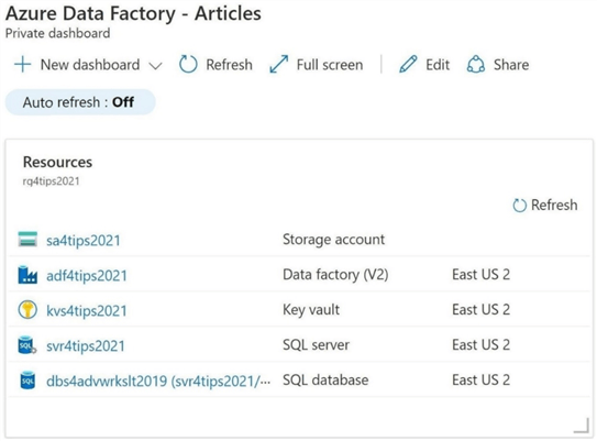
I will not be reviewing how to deploy these objects to the subscription. However, the table below lists each object, the purpose of each object and where to find more information about deployment on the MSSQLTips website.
| No | Type | Name | Description | Link |
|---|---|---|---|---|
| 1 | Resource Group | rg4tips2021 | Group objects by this container. | Tip-01 |
| 2 | Storage Account | sa4tips2021 | Group containers by this account. | Tip-02 |
| 3 | Storage Container | sc4tips2021 | Use hierarchical name spaces. | Tip-02 |
| 4 | Key Vault | kvs4tips2021 | Save key information. | Tip-03 |
| 5 | Data Factory | adf4tips2021 | Design ELT pipelines. | Tip-04 |
| 6 | Logical SQL Server | svr4tips2021 | Group database by server. | Tip-01 |
| 7 | SQL Database | dbs4advwrks2019 | Example database in cloud. | Tip-01 |
Now that we have a test development environment, we will need to configure the environment for our first pipeline.
Data Lake Storage
Nowadays, I spend a lot of time designing pipelines with Azure Data Factory (extract and load) or Notebooks (translate) with Azure Databricks. Regardless of the technology, we need to create directories to store our files.
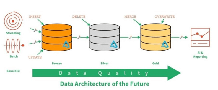
The data lake image below was taken from the Databricks website. In a typical lambda architecture, we might have both batch and streaming data being landed into the data lake. In short, the quality of the data increases as you move from one zone to another. Sometimes the concepts of raw, refined and curated zones are used instead of metals to described quality.
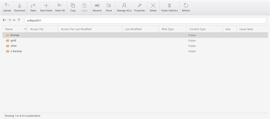
The developer must define the quality zones or topmost folders for the lake. This can be done by using Azure Storage Explorer. The image below shows all three zones. Additionally, I created a z-backup directory to hold backups of the Adventure Works LT schema and data.
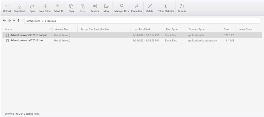
The image below shows two ways in which the database has been backed up. The following links show how to create a bak and bacpac file using SSMS.
In the next section, we will restore the Adventure Works LT 2019 database from a bacpac file using the Azure Portal.
Azure SQL Database
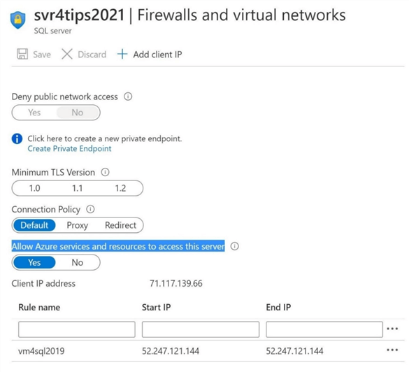
Azure Data Factory can only work with in-cloud data using the default Azure integration engine. Therefore, I have chosen to use a serverless version of Azure SQL database to house our sample database. With a new logical server deployment, one must make sure firewall settings are correctly chosen. Please give Azure services and resources access to the server. Also, any Azure Virtual Machines should be whitelisted by internet protocol address. Please see the image below for details on a sample firewall rule.
From the Azure portal under the svr4tips2021 logical server, please choose to import the bacpac file as a new database. Unfortunately, one cannot change the name of the destination database at this time. However, the developer can rename the database later using SQL Server Management Studio (SSMS).
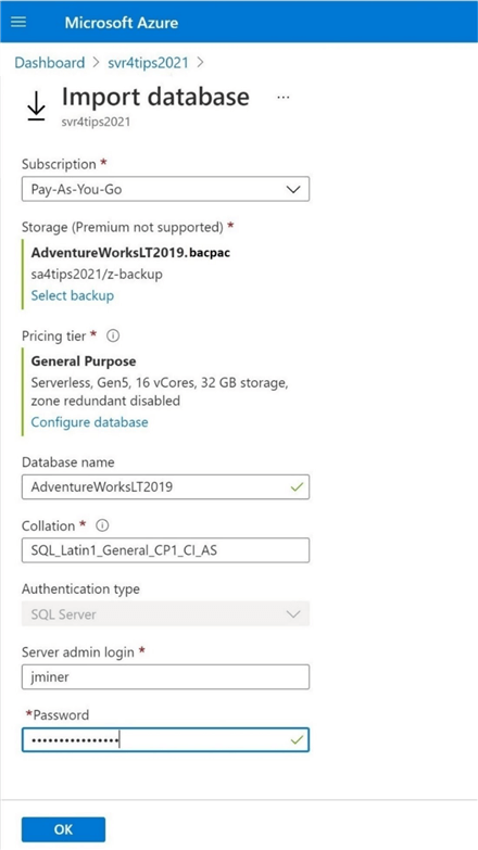
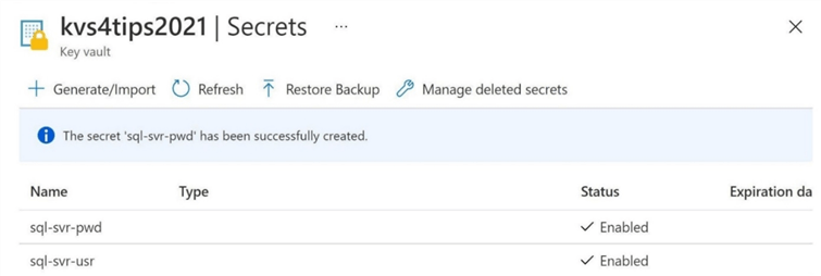
Within the import dialog box, the developer will be prompted to choose the username and password for the administrator. Place this vital information into the key vault. Since I work with many different clients, this service is invaluable in locating passwords for a client I have not worked with in a while.
Click the okay button to start the import process.
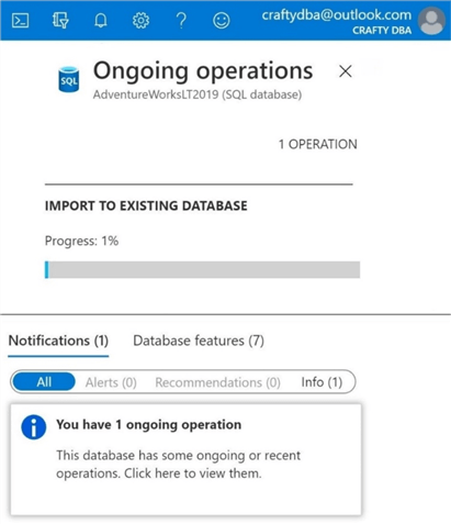
The overview tab of the database will show information about the import process. There is a centralized service by Azure Region that executes theses common requests. Depending on bacpac size and cloud load, the restore process can take several minutes. I captured a screen shot that shows an ongoing import operation. The database was at 1 percent when I capture the picture.
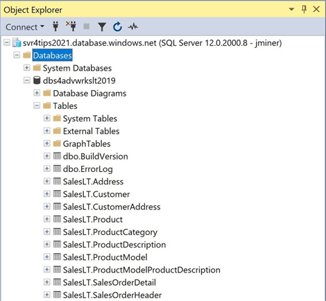
To finish the task, I renamed the AdventureWorksLT2019 database using SSMS to conform to my naming convention. The image below shows the dbs4advwrkslt2019 database deployed within the svr4tips2021 logical server.
Now that we have configured the source (Azure SQL Server) and the target (Azure Data Lake Storage), we can finally start crafting our first ADF pipeline.
Source Data Set
The image bellow shows the relationships between all objects in Azure Data Factory (ADF). Traditional pipelines in Azure Data Factory that do not use mapping data flows or wrangling data flows are considered an Extract, Load and Transform (ELT) process. That means ADF can orchestrate the copying of data from the source to the target. However, any transformations will have to be handled by another service such as Azure SQL Database stored procedures or Azure Databricks Notebooks.

The first task of our first pipeline program is to define the source linked server and source data set.
All data sets are defined by starting with a linked service definition. One can think of the linked service as the connection string for a given source or target. Our sample business case has the Adventure Works LT database as the source. Therefore, please define a linked service by using the following menu path in ADF: Manage, Linked Services, New, Azure, and Azure SQL Database.
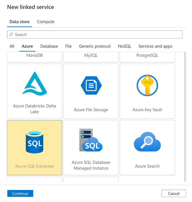
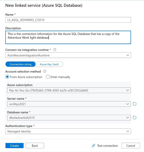
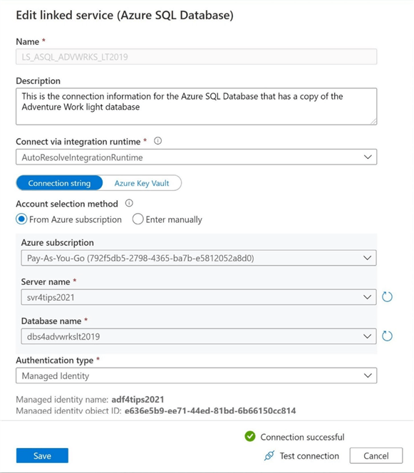
There are many ways to configure a linked service. In my opinion, a managed identity is the best way to set up access between two Azure Services. This authentication type eliminates the need to manage credentials such as a username and password. Microsoft Azure is responsible for managing this for you. I choose to create the connection string by navigating thru the objects in my Azure Subscription using the provided dropdown boxes.
Always try testing the connection before creating the linked service. We can see from the error message below that either the firewall is blocking the connection, or the token identified principle (managed identity) does not have access to the database. We know it is not the firewall since we configured those settings already.
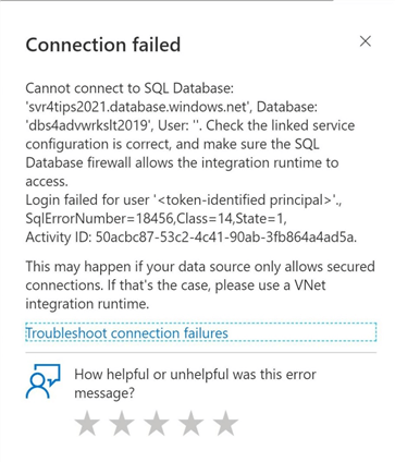
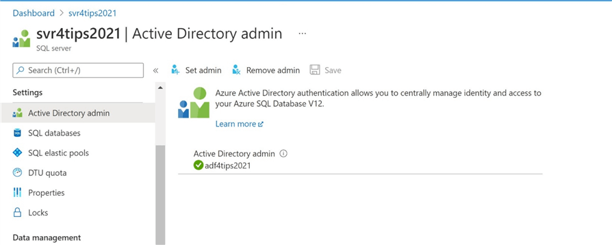
The easiest way to fix this issue is to elevate the manage identity named adf4tips2021 to the Active Directory administrator for the logical SQL server. However, this is not a good practice since the account only needs read access to the database. A better way to solve this problem is to add the managed identity as an external user of the database and assign it to the correct database role. Please see this MSDN article for details on the right way to give out security for the managed identity account.
If we re-test the connection, will get a successful test. What you might not have noticed is the use of a standard naming convention. I use the naming convention from Navin’s web page. It is a good reference on how to prefix the objects one defines in Azure Data Factory. The name LS_ASQL_ADVWRKS_LT2019 tells the developer that it is a Linked Server for Azure SQL Database, and it happens to be pointing to the Adventure Works LT 2019 database.
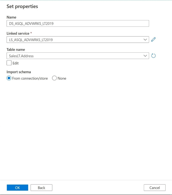
The next task is to create a source data set given the newly created source linked service. Please navigate using the following menu path in ADF: Author, Data Set, and New Data Set. Again, choose the Azure and Azure SQL Database as the type of source. Please note that the prefix of LS has been replaced with DS for the data set name. This full name, DS_ASQL_ADVWRKS_LT2019, tells the developer that the object is a dataset for an Azure SQL database table. Choose the correct linked service and correct table name by using the edit and dropdown boxes.
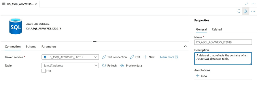
Finally, it is very important to add descriptions to all the objects that you define in Azure Data Factory. We can optionally test the connection again or preview the data right now. The source data set reflects only one static table. After we completely build our first pipeline, we will revisit this dataset to make it dynamic by using a parameter. That is why I am leaving the name of the data set very generic in nature.
In the next section, we will work on defining the target linked service and target data set.
Target Data Set
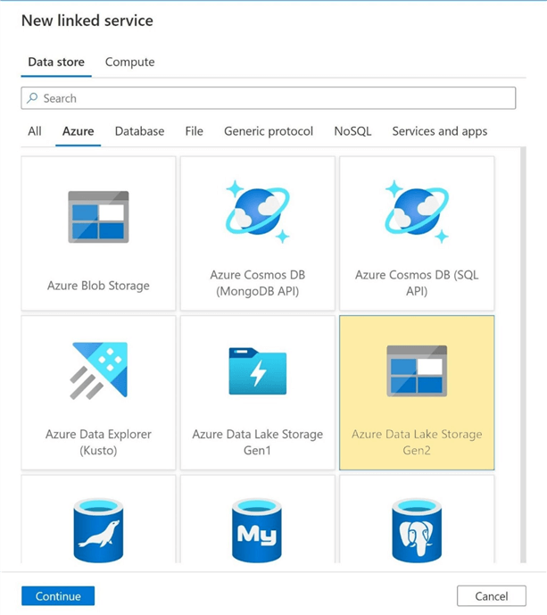
The second task is to define the target objects before we can create a pipeline with a copy activity. Our target data set is a file in Azure Data Lake Storage. Therefore, please defined a linked service by using the following ADF menu path: Manage, Linked Services, New, Azure, and Azure Data Lake Storage Gen2.
The most important part about designing pipelines is to stick with a consistent naming convention and clearly document all the objects. The image below shows the new linked service is named LS_ADLS2_DATA_LAKE_BRONZE_ZONE and the description aptly documents the connection.
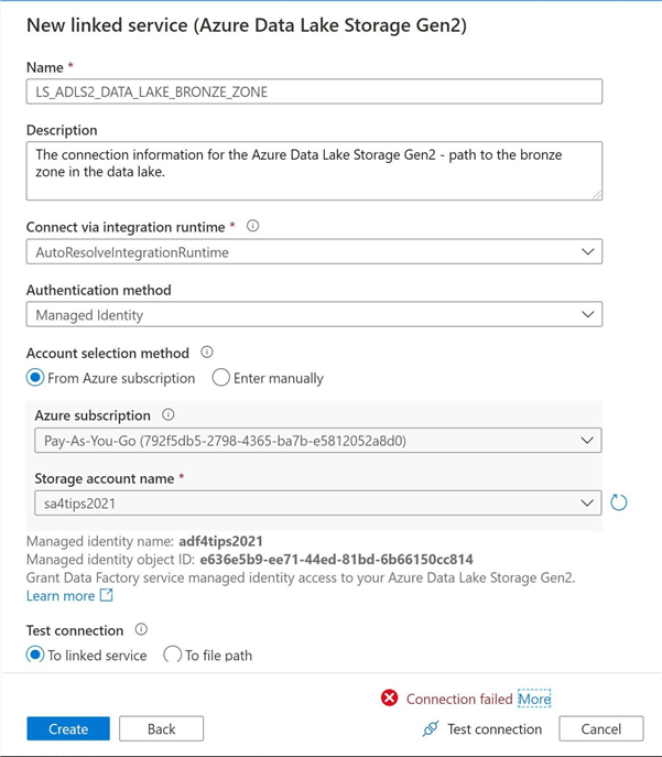
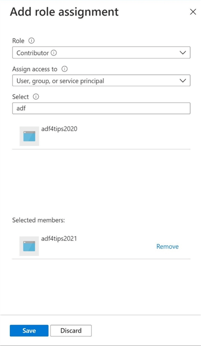
Before saving the connection, please click the test connection button. We noticed that the connection fails. The first level of security for the Data Lake Storage service is Role Based Access Control (RBAC). If this account is going to read and write to storage, we need to give the managed identity contributor rights to the storage account. The image below shows the correct action to fix this issue. For more information, please read this MSDN article on security for Azure Data Lake Storage.
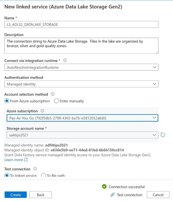
If we retest the connection, we can see that it has had a successful test.
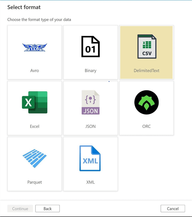
The next task is to create a target data set given the newly created target linked service. Please navigate the following ADF menu path: Author, Data Set, New Data Set, Azure and Azure Data Lake Storage. There are many types of files that can be created in the data lake. We are going to select the Delimited format as the file type. The default delimiter is the comma. However, this can be changed to any character that we want.
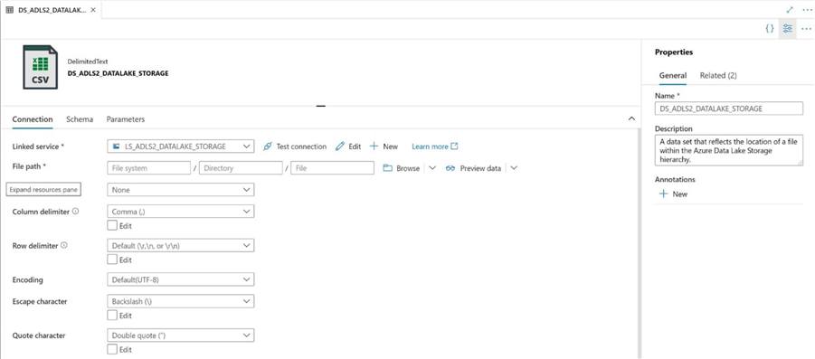
Please note that the prefix of LS has been replace with DS. This full name, DS_ADLS2_DATA_LAKE_BRONZE_ZONE, tells the developer that the object is a file in the raw zone of the data lake. Choose the correct linked service from the dropdown menu. Also, use the browse button to select the final location of the file.
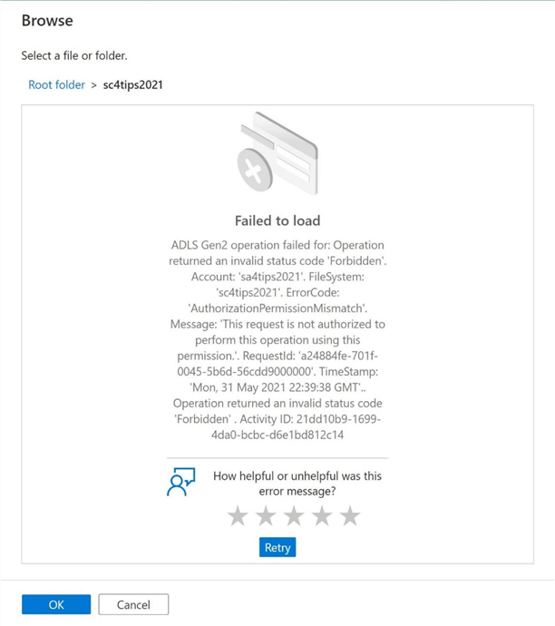
The error message below states that we do not have authorization to browse files in the sc4tips2021 container. The second level of security for Azure Data Lake Storage is the Access Control List (ACL). To correct this issue, we must give the managed identity read and write access.
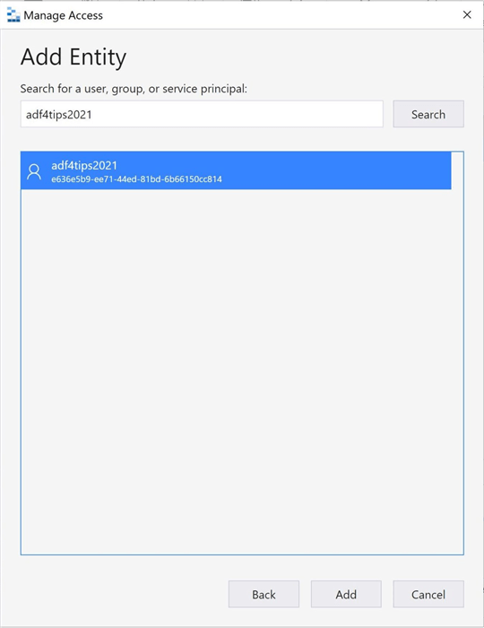
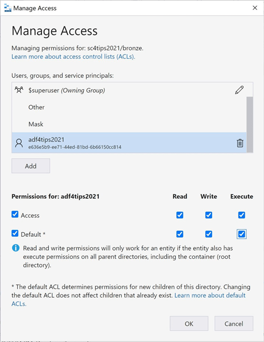
We can use the Azure Storage Explorer with an elevated account to assign rights to the container and all sub-directories. Right click the container or folder to bring up the manage access menu. The dialog box below can be used to search for the managed identity account.
The image below shows the assigning of rights to the bronze folder. There are two type of permissions that can be given out. Access refers to changing the current rights. Default refers to allowing the rights to be inherited by child folders and files. Three types of ACL rights that can be assigned are read, write and execute.
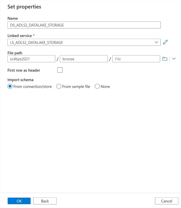
If we retry browsing for the file path, we should now be about to set the root container to sc4tips2021 and the file path to bronze.
Static Pipelines
Any pipeline that is called multiple times and produces the same result can be termed static in nature. Today, we are going to create our first version of the pipeline program using hard coded parameters.
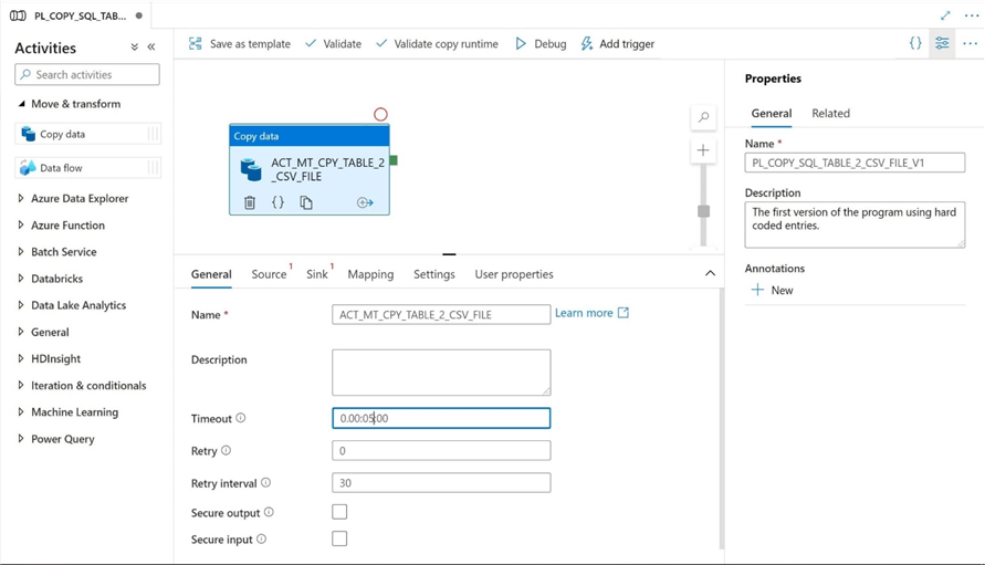
The copy activity is the bread-and-butter operation of any ELT pipeline. It can be located under the move and transform menu. Drag the icon from the menu to the pipeline work area to get started. Please note, the name ACT_MT_CPY_TABLE_2_CSV_FILE tells everyone that the activity copies table data to a csv file format. The PL_COPY_SQL_TABLE_2_CSV_FILE_V1 is the long name associated with the pipeline. Please make sure that you change the timeout value for the copy action. By default, the timeout is set to 7 days. I am choosing to set this value to 5 minutes since the tables are very small.
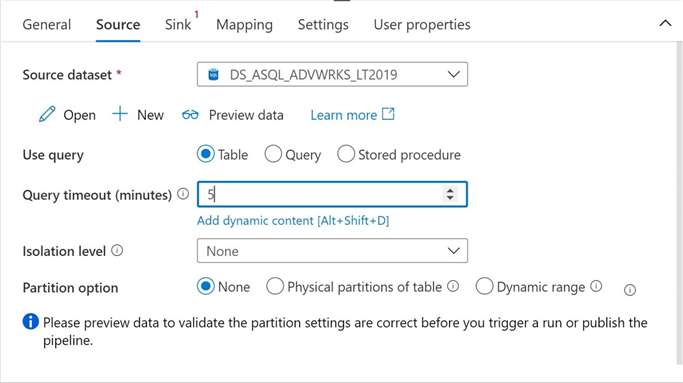
We need to define both the source and sink of the copy activity. Please select the DS_ASQL_ADVWRKS_LT2019 data set as the source and change the query timeout to 5 minutes. Currently, the source table name is hard coded in the data set.
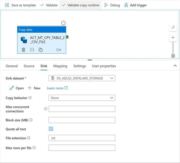
Tab over to the definition menu for the target (sink) data set. We can see that the DS_ADLS2_DATALAKE_STORAGE data set does not allow us to provide a target file name. We forgot to define one when we created the object. Let us go back to the dataset definition and resolve this issue.
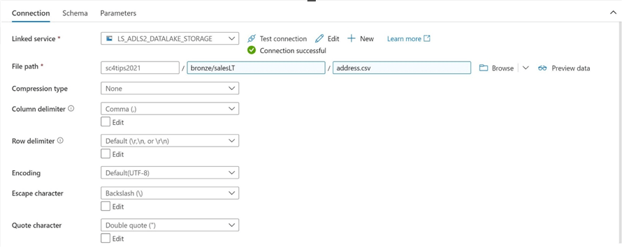
The image below shows the target data set being updated with a directory path and file name.
Please click the debug button on the pipeline to start an execution of the pipeline. The image below shows the output of the debug session. Our first pipeline completed the execution successfully.

If we use Azure Storage explorer, we can see that the address table data has been saved as a delimited file in the saleslt directory.

In a nutshell, hard coded pipelines are easy to create. However, they are not that very useful since we will need to define a source data set, target data set, and copy pipeline for each table that we want copy to the lake. In the next, section we will go over how to use parameters to make the pipeline dynamic in nature.
Dynamic Pipelines
Any pipeline that is called multiple times and produces the different results given different inputs can be termed dynamic in nature. Today, we are going to create our second version of the pipeline program leveraging parameters.
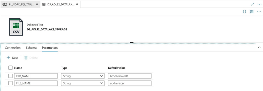
The first task is to revisit both the source and target data sets. We could define a source data set parameter for both SCHEMA_NAME and TABLE_NAME; However, dynamic Transaction SQL is more flexible to use in the copy activity. I will focus on creating target data set parameters named DIR_NAME and FILE_NAME. The image shows the default values for these two parameters.
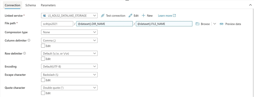
The connection information for the file path of the target data set must be changed to leverage these new parameters. Use the "add dynamic content" link to open a dialog box in which an expression can be crafted. Choose the appropriate parameter for both the Directory name and File name. See image below for details.
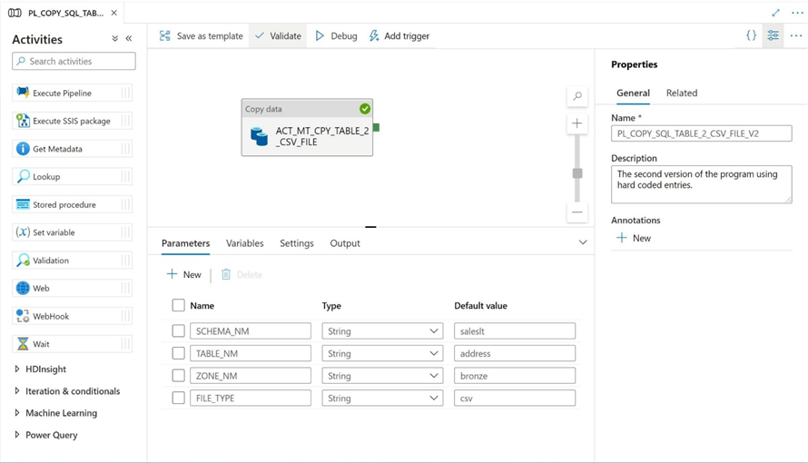
Parameters can also be defined at the pipeline scope. The schema name, table name, zone name and file type are properties that can be parameterized. Unlike variables, parameters can be defined as many different data types as possible. Variables only support the String, Boolean and Array data types. The image below shows the parameters to the pipeline are all defined as strings.
To make this pipeline have a truly dynamic data source, we can change the source of the query. Instead of table, please use query option. Please use the "add dynamic content" link to enter the following expression.
@concat('select * from ', pipeline().parameters.SCHEMA_NM, '.', pipeline().parameters.TABLE_NM)
This code returns a basic select statement that returns all rows for a given schema and table.
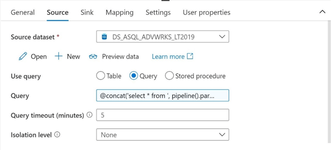
Now that have the source dataset defined as a dynamic expression, let us finish the job by making the target data set use expressions to dynamically define the data set parameters.
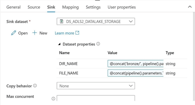
The expression below sorts the output files into sub directories by schema and name. Remember, the first version of the pipeline program dropped all the files in a directory named after the schema, saleslt. In real life, one might want to create an additional sub directory based on year and month such as YYYYMM underneath the table name. Any given month might have more than 28 files per table name. This allows for the users of the data lake to easily find files.
@concat('bronze/', pipeline().parameters.SCHEMA_NM, '/', pipeline().parameters.TABLE_NM)
The expression below uses the utcnow function to add a date time stamp at the end of the final file name. In this version of the pipeline, we are only outputting one target file format which happens to be csv delimited. In the future, we can use this FILE_TYPE parameter to allow for the program to output different file types.
@concat(pipeline().parameters.TABLE_NM, '-', replace(replace(substring(utcnow(), 0, 19), '-', ''), ':', ''), '.', pipeline().parameters.FILE_TYPE)
The image below shows the finalized definition of the sink data set using ADF expressions.
If we execute the program right now, we end up with a delimited file in a sub directory named after the schema and table. Additionally, a date and time stamp have been added to the end of the file. This allows for the business use case that needs near real time execution. If we are getting a new file every hour, then we might have 24 files per a given day. The number of files increase as the time duration decreases.

To recap, parameters allow for both the source and target locations to be dynamic in nature.
Scheduling Pipelines
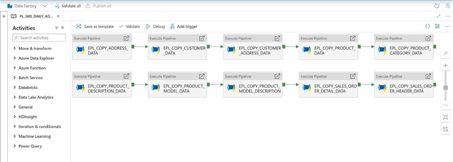
Version two of the pipeline program allowed for the copying of any Adventure Works table to a csv file in the data lake. How can we automate this process to copy over all tables from the Adventure Works LT 2019 database and land them as csv files in the data lake? The solution to this problem is to create a scheduling pipeline. Instead of using ACT_GEN_EPIPE for execute pipeline per our naming convention, I am using EPL and the COPY action word. There is a limit to the number of characters when naming objects. The image below shows 10 separate calls to copy over the 10 tables to the data lake storage.
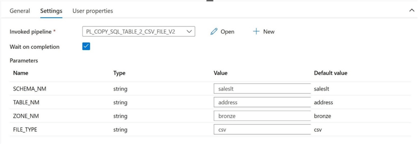
The details of the execute pipeline call are shown below. This image shows the parameters used to copy over the address table.
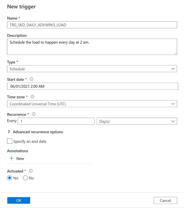
To run the schedule pipeline on a periodic basis, we need to create a new trigger. Please see this MDSN documentation link for more details. Again, naming conventions and comments are important. I am going to schedule the execution of the main schedule pipeline, PL_SKD_DAILY_ADVWRKS_LOAD to run every day at 2 am.
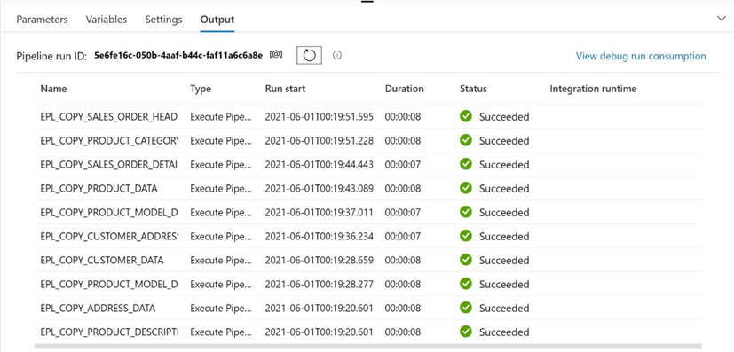
We can manually kick off a debug session to test the main schedule pipeline. The output below shows the successful execution of all 10 tables.
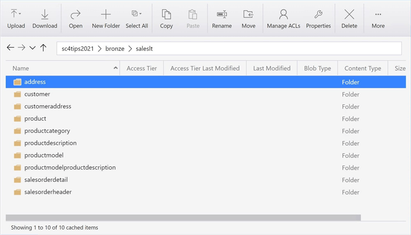
One last task is to look at Azure Data Lake Storage using the Storage Explore. The image below is a screen shot of the saleslt sub-directory. There are now 10 sub-directories representing each of the tables in the Adventure Works LT 2019 database.
Summary
Azure Data Factory is a simple Extract, Load and Translate program. At its core, the developer needs to define both a source and target data set. The most common activity is the copy command. This allows the developer to move data from one location to another. The number of connectors available in Azure Data Factory make the tool very attractive to data engineers.
The first version of the pipeline program was a simple copy of a single table from Azure SQL Server to Azure Data Lake Storage. This program used hard coded information when defining the source and target data sets. Therefore, the execution of the program generated the same results. For copying large amounts of tables to the data lake, this design pattern is not optimal. It requires new objects for each table. The total amount of code might become unmanageable with this framework.
The second version of the pipeline program used parameters for both the data sets and pipeline. I chose not to show how to parameterize a table data set with a schema name and a table name. Instead, I focused on dynamic Transaction SQL (T-SQL) which is more useful. In today’s examples, we focused on bringing all the records over from the table to the data lake. This is called a full load type and works great for small to medium size tables. For an incremental load type, we will need to filter the data using a where clause and a watermark. Therefore, using a dynamic query up front makes more sense.
To leverage the dynamic nature of the copy pipeline, a schedule pipeline was created to repeatedly call the pipeline with the correct parameters. Two sets (lists) of connected activities were drawn in the pipeline. That means that at most, two pipelines will be running at a given time in parallel. Today was our first adventure in advanced ADF programming. Please stay tuned for more exciting articles to come this summer.
Enclosed is Azure Resource Management (ARM) template export of all the Azure Data Factory objects that were created today.
Next Steps
- Using conditional activities to support multiple output file formats.
- How to create parquet files when using the self-hosted integration runtime.
- Partitioning source data tables for faster transfer times.
- Preventing schema drift with the tabular translator mapping.
- Custom execution, error and catalog logging with Azure Data Factory.
About the author
 John Miner is a Data Architect at Insight Digital Innovation helping corporations solve their business needs with various data platform solutions.
This author pledges the content of this article is based on professional experience and not AI generated.
View all my tips
Article Last Updated: 2021-06-25


